Upgrading your Apogee Symphony MKII from TB2 to TB3: Need to Knows
Upgrading your Apogee interface to Thunderbolt 3 isn’t difficult — but it’s not a casual five-minute job either. This guide walks you through what the installation involves and what you’ll need to be successful.
Let’s be clear: If your Thunderbolt 2 setup is working fine, it is not a requirement to upgrade. If you have good working cables and a Thunderbolt 2 to 3 adapter, that setup is absolutely compatible with modern Mac computers. The performance between the two is identical. This said Thunderbolt 3 can simplify life simpler if you’re using newer computers, want to get rid of adapters, need to run longer optical style thunderbolt cables or are concerned long term in finding TB2 replacement cables that are no longer manufactured and thus hard to find.
If you do decide to upgrade, the key to a successful install is being methodical, organized, and a little bit handy.
TL; DR – Can I do it Myself or should I send it in?
The short answer is: Yes, BUT the install does require patience, some finesse and an appropriate workspace and process for not losing parts or track of the steps. Here’s what to expect. As an overview completing the install involves:
Project Outline:
- Removing the top panel (14 screws)
- Removing the rear panel (3 screws on bottom, 4 on the sides)
- Removing the ground from the interior side panel
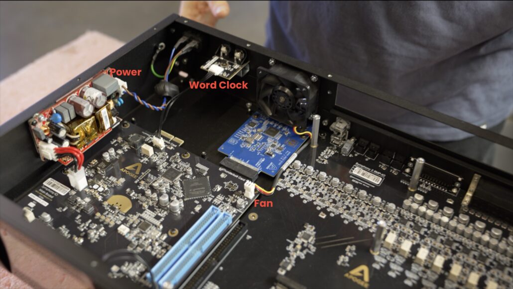
- Disconnecting components from the rear panel:
- Power Inlet
- Word Clock
- Cooling Fan
- Transferring components to the new TB3 back panel
- Removing the TB2 Option Card
- Inserting the new TB3 Option Card
- Reinstalling the back panel
- Reconnecting quick connect cables to their appropriate places
- Reaffixing bottom and side screws
- Reattaching the top panel
It’s not hard, but it is detailed and hands-on. If you’re not confident about the process, it may be better to send in or consult Apogee support.
What You’ll Need
- Clean workbench or table with good lighting
- Screwdrivers (Phillips #1 and small-head for tight spots)
- Small tray or magnetic dish for screws
- New Thunderbolt 3 card and replacement back panel
- Patience
Screw breakdown by type
Before you open the unit, it helps to know what types of screws you’ll encounter:
| Screw Type | Used For | Notes |
| Flat-head | Exterior chassis (top, sides, bottom) | Most common type. 14 top panel screws, 4 side screw and 3 bottom screws. |
| Round-head | Option cards, modules, Thunderbolt card, ground wire | Used for internal Thunderbolt card, ground, and securing modules or blank panels. |
| Specialized screws | Word Clock | Two unique screws: one short flat-head screw, one long threaded screw into a plastic mount. |
| Captive nut screws | Fan Assembly | 4 screws paired with small nuts; holds fan and grille guard to chassis. |
Who Should (and Shouldn’t) Do This
This is a doable upgrade for musicians, engineers, or techs who:
- Are comfortable with electronics and small screws
- Are confident they will not strip screws
- Have a tidy workspace and patience
It may not be for you if:
- You are easily frustrated by detailed mechanical tasks
- You do not have an adequate workspace for the install
There’s no shame in asking for help. Those who want to update but would rather have us take care of it can request an install from Apogee Support.
Step-by-Step Guide: Thunderbolt 3 Card Installation
Step 1 – Power Down and Prep
- Unplug Everything: power, DB25s, optical cables, USB, etc.
- Let the unit cool for 5–10 minutes.
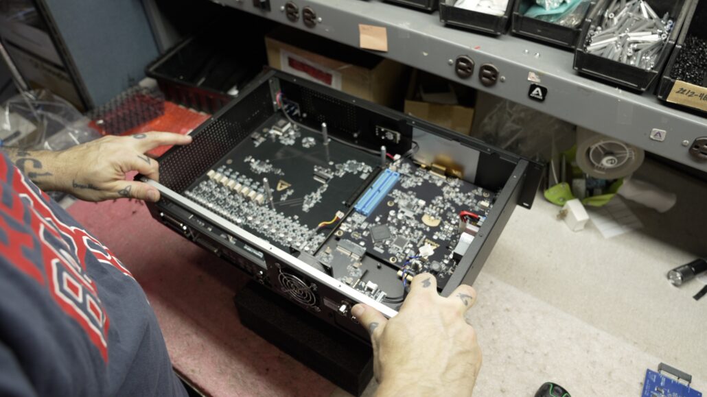
- Clear a space to lay the unit down flat. You’ll need room to flip and rotate it.
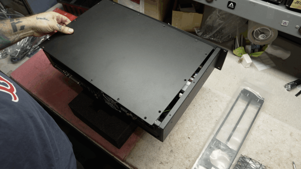
Step 2 – Remove the Top Panel
- Unscrew the 14 flat-head screws securing the top.
- Set them aside — you’ll reuse them during reassembly.
Step 3 – Remove the Rear Panel Screws
If you have modules or an option card (like Dante, Pro Tools, or Pro Tools Plus), you do not need to remove them from the chassis.
However, you do need to remove the round-head screws that secure these cards or blanks to the rear panel.
The option cards and modules remain mechanically and electrically connected to the internal board.
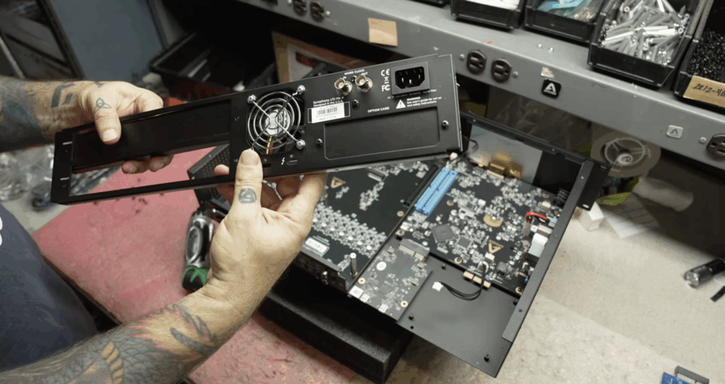
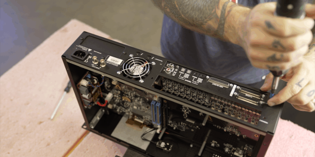
Step 4 – Remove the Rear Panel
For the rear panel to separate from the chassis, remove the following screws:
- Two screws per side from the side panels
- Three screws from the bottom panel
- One screw securing the ground wire to the side panel
- Carefully pull the panel away from the chassis
Pro Tip: If you’re unsure whether your panel is free, gently tug — nothing should resist. If it does, check for missed screws.
Important: Do not let the rear panel hang. Cables to the fan, word clock, and power inlet are still attached. Support the panel with one hand or rest it on a softy against the chassis during the next step.
Step 5 – Disconnect Rear Component cabling
You will need to disconnect three internal cables:
- Fan cable – disconnect the connector cable then guide cable tucked underneath the Thunderbolt cord so it hangs above
- Word clock cable
- Power inlet
Pro Tip: Take close-up photos of these connectors and their orientations before removing. It makes reassembly much easier.
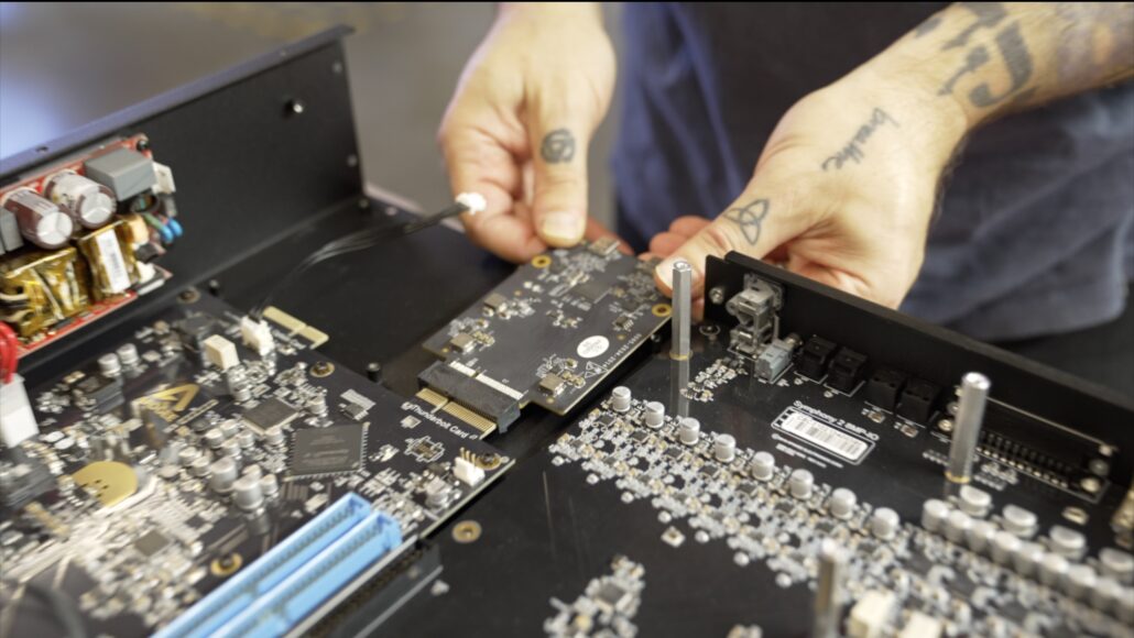
Step 6 – Remove the Thunderbolt 2 Card
Locate the Thunderbolt card
Unscrew the two round-head mounting screws
Slide the card out slowly and slightly upward to avoiding scraping components on the bottom side of the card
Step 7 – Remove Components from the old TB2 Back Panel
Dismount these three components from the old rear pane, the order can be done in your preference but remember the fan and word clock screws are specific to those parts:
- Power inlet
- Depress the tabs and push the component through.
- Word clock
- Remove the two screws of different sizes.
- Fan
- Remove 4 screws and corresponding nuts. Beware that the gasket does not pull out of place, fan removes towards interior, guard removes towards exterior.
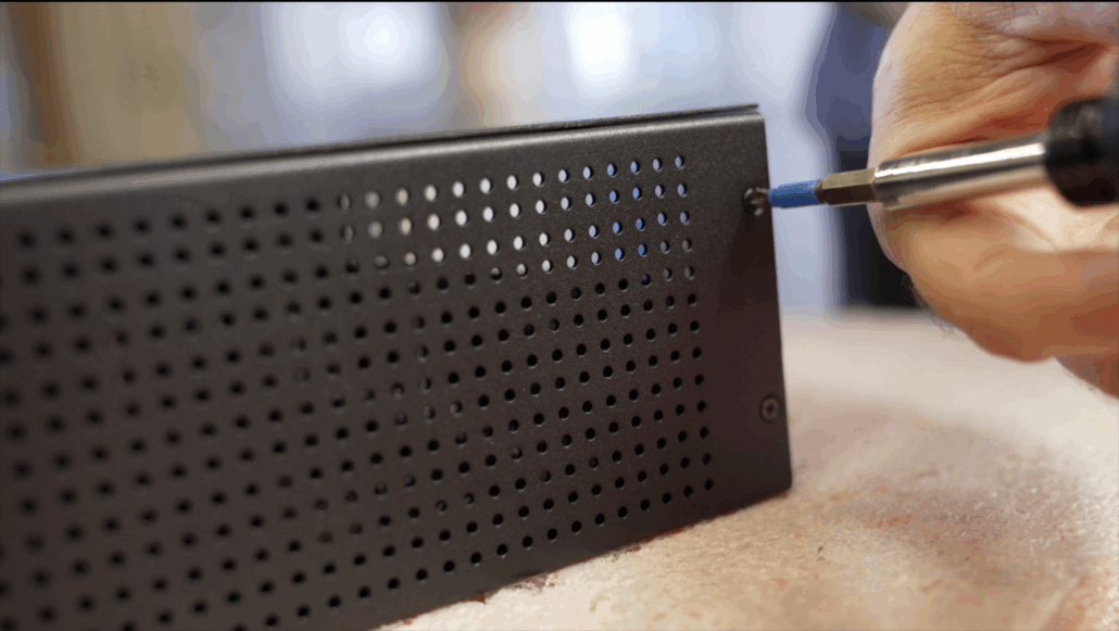
Step 8 – Mount Components to the new TB3 Back Panel
- Power inlet
- Guide cables from the exterior through, into the interior. Inlet will snap into place as tabs clear.
- Word clock
- Remove the two screws of different sizes.
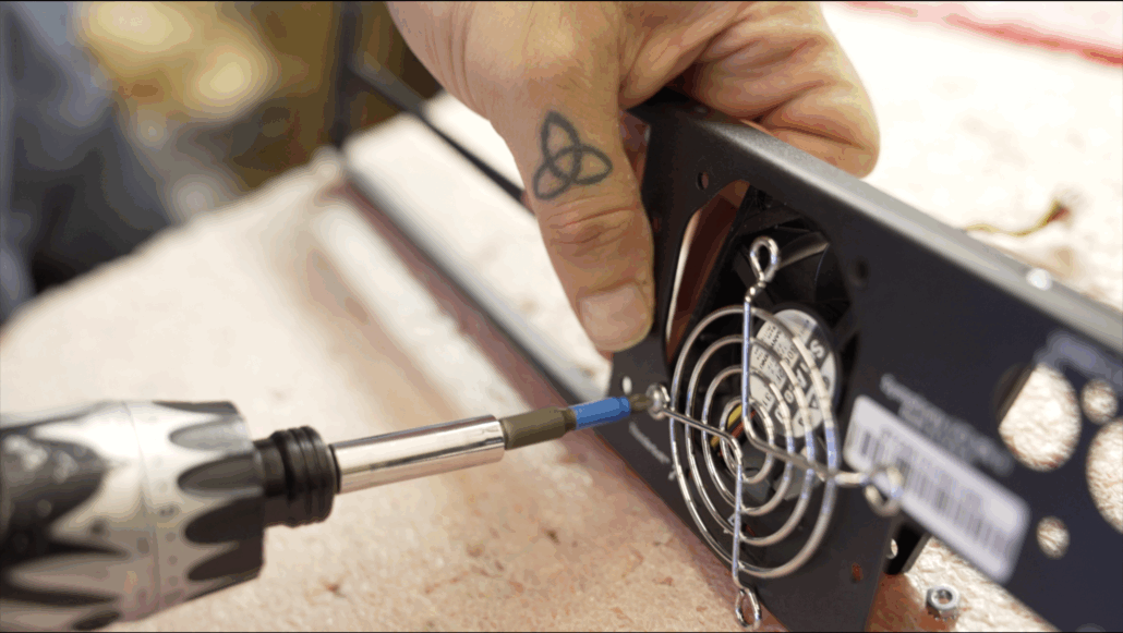
- Fan
- Position the nut into place on the back, place fan flush to panel from interior and place grille guard on exterior. Thread the screw into the nut. Repeat the process for all 4 screws, being careful not to overnight screws and warp the guard cutouts.
Pro Tip: The fan is the trickiest part. The screws are short, and the space is tight. Use a small-head screwdriver and take your time.
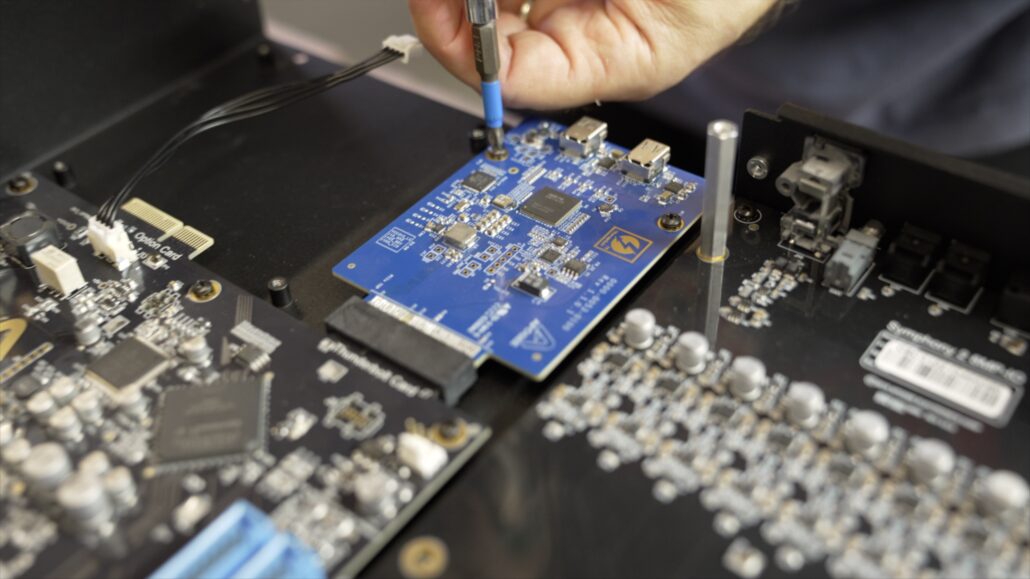
Step 9 – Install the Thunderbolt 3 Card
Slide the new TB3 card into position. Beware to avoid scraping the underside while positioning.
Don’t screw it down yet — wait until the rear panel is installed and aligned
Step 10 – Reinstall Rear Panel and Chassis
- Position the rear panel so that it lines up with the thunderbolt card and fits into rear and bottom panels
- Ensure the Thunderbolt 3 ports line up cleanly with cutouts and allows for cables to be easily inserted, card can be wiggled slightly to better align ports if not properly lining up.
Reattach screws to Side panels (2 per side) and bottom panel screws
Reattach Ground wire with round-head screw
Step 11 – Reattach Cabling from rear panel Components
Reconnect cables:
- Fan (tuck excess cable out of the way)
- Power inlet
- Word clock
Step 12 – Affix Modules and Top Panel Reattach Cabling from rear panel Components
For any installed additional option cards or modules, affix to chassis from exterior using round head screws.
Secure the top panel with the 14 flat-head screws
Final Thoughts
We hope this guide helps you understand what this upgrade/ install involves and what to look out for and expect as you go through. For those looking to follow along with video, please watch this rundown. Happy upgrading!